+8618234403483
 yanzhang19990421@gmail.com


Working Principle of 5 Types Of Flotation Machines
 shirley
 Nov 06, 2020
 12812
12812
If you want to know more details about equipment, solutions, etc, please click the button below for free consultation, or leave your requirements!
 Message
 Chat Now
Commonly used flotation machines can be divided into five categories: mechanical agitation flotation machine, inflatable agitation flotation machine, flotation column, impeller flotation machine and rod flotation machine. This article will introduce the working principles of these five types of flotation machines one by one to help you choose the right flotation cell for your beneficiation plant.

01 Mechanical Agitation Flotation Machine
BackThe slurry and the flotation reagent are fully mixed and fed into the bottom of the cell of the first chamber of the mechanical agitation flotation machine. When the impeller of the flotation machine rotates, negative pressure will be formed in the wheel cavity.
The slurry either in the bottom of the cell or in the middle of the cell is brought into the mixing zone by the lower and upper suction ports of the impeller respectively. The air then enters the mixing zone along the air guide sleeve. In the mixing zone, the pulp, air and flotation chemical are mixed.
Under the action of the centrifugal force of the impeller, the mixed pulp enters the mineralization zone, and the air bubbles is squeezed to make full contact with the materials to form mineralized bubbles. Under the action of the stator and the turbulence plate, the mineralized bubbles are evenly distributed in the trough section, and then move up into the separation zone, enriched to form a foam layer, and the foam layer is discharged by a bubble scraper to form a concentrate foam.
The unmineralized material on the bottom of the cell will be mixed, mineralized and separated again through the circulation hole and the upper suction port. The slurry under the cell that is not sucked by the impeller of the flotation machine enters the bottom of the second chamber through the middle ore box buried in the slurry. After all the processes in the first chamber are completed, it enters the third chamber. And the flotation equipment repeats the operation in each cell until the pulp enters the tailings box to discharge the final tailings.

02 Inflatable Agitation Flotation Machine
BackThe aerated stirring flotation machine relies on a motor drive and a hollow main shaft to drive the impeller to rotate. The slurry in the trough is sucked into the lower blades of the impeller through the bottom of the trough through the inner edge of the lower blade of the impeller.
At the same time, the low-pressure air supplied from the outside enters the air distribution of the lower impeller cavity through the beam, air regulating valve and hollow main shaft. Then, it enters between the lower blades of the impeller through the small holes around the air distributor. After the pulp and air are fully mixed between the lower blades of the impeller, they are discharged from the outer edge of the lower blades of the impeller.
Due to the joint action of the rotation of the flotation machine impeller, the cover plate and the center tube, a certain negative pressure is generated in the upper blade of the impeller, so that the medium ore foam and fed ore flow into the center tube through the medium ore pipe and the ore feed pipe respectively. And then the foam enters the upper blades of the impeller, which is finally discharged from the outer edge of the upper blade.
The pulp discharged from the outer edge of the lower blade of the impeller is first mixed with air, and then flows through the stator and oriented together with the medium ore and feed ore discharged from the outer edge of the upper blade of the impeller, and then enters the main pulp in the cell.
The mineralized bubbles rise to the surface of the pulp to form a foam layer. A part of the pulp returns to the lower blades of the impeller for recycling, and the other part enters the next cell through the circulation holes on the wall between the tanks for re-selection or discharge as a final product.

03 Flotation Column
BackAfter the pulp and flotation reagent are fully mixed, they are sent to the flotation column through the central feeding device. The pulp is slowly descended under the action of gravity, and the compressed air is dispersed into a large number of tiny bubbles through the inflator, which are evenly distributed on the entire section of the column and rise slowly. At this time, the slurry and bubbles form a convective motion.
In this case, a part of the floatable minerals adhere to the bubbles and rise to the top of the slurry to form mineralized bubbles, and overflow from the foam launder or use a scraper to scrape the foam out of the concentrate. The other part of the non-floating gangue cannot be attached to the air bubbles and is discharged from the tailings lifting device or enters the next operation.

04 Impeller Flotation Machine
BackThe slurry is fed into the impeller flotation machine through the slurry inlet pipe, and then thrown into the cell by the centrifugal force generated by the rotating impeller, so a negative pressure is formed under the cover plate, and air is automatically sucked in by the inlet pipe. The sucked air and the fed pulp are mixed in the upper part of the impeller and then thrown back into the cell, again generating negative pressure, sucking in air, and repeating until the next operation.
Under the action of flotation reagent, the minerals to be floated are brought to the surface by bubbles to form a mineralized foam layer, which is scraped out by a scraper to obtain a concentrate. The non-floating minerals and gangue enter the intermediate chamber through the gate on the side wall of the tank and are fed into the next flotation tank. The adjustment of the slurry level in the tank can be completed by adjusting the gate up and down, and the slurry completes the circulation process in the impeller flotation machine.
05 Rod Flotation Machine
BackThe rod flotation machine relies on the motor and pulley to drive the inclined rod wheel (installed at the lower part of the hollow shaft) to rotate. When the inclined rod wheel rotates at a high speed, negative pressure will be generated in the float wheel, and the air sucked in by the hollow spindle will be divided into tiny bubbles by the float wheel.
Under the strong stirring and projecting action of the flotation wheel, the pulp and air are fully mixed. This slurry-gas mixture is propelled forward by the force generated by the inclined rod of the flotation wheel, and then is evenly distributed in the tank by the diversion action of the boss (gland) and the arc-shaped plate stabilizer. Under the reflection effect of the bottom and the groove wall and the steady flow effect of the arc-shaped plate, it rises from the stirring zone to the liquid surface through the separating zone.
Seen from the longitudinal section of the trough, the flow trajectory of the slurry-gas mixture is in a W shape. This flow characteristic makes the range of the stirring zone relatively enlarged and the range of the separating zone relatively reduced. In addition, the shallow tank makes the range even narrower.
The former increases the chance of contact between mineral particles and bubbles, which is beneficial to the mineralization of the foam. The mineralized foam rises to the foam area and is scraped out to become a foam product. The working principle of the suction tank is the same as that of the vertical sand pump, that is, the pressure head is generated by the rotating lifting wheel, and the slurry is sucked from the draft tube at the bottom of the tank and lifted to the required height.

06To Wrap Up
BackAbove we talked about working principles of the five commonly used flotation machines. The specific choice of which type of flotation machine needs to be considered in combination with many factors such as the nature of the ore, the process flow, and the recovery index. If you want to select a suitable model, it is recommended to consult a beneficiation equipment manufacturer with mine design qualifications to avoid economic losses.
If you have any questions about the above issues or you want to get advice on flotation machine selection, please leave a message to communicate with us or consult our online customer service, we will contact you as soon as possible.


RELATED PRODUCTS
-
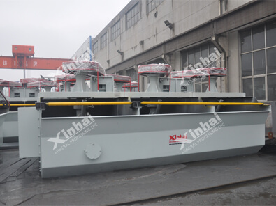
SF Flotation Cell
-
JJF Flotation Cell
-
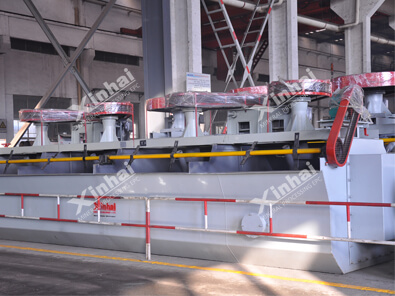
BF Flotation Cell
RELATED POSTS
-
 Laura
Jul 20, 2026
Laura
Jul 20, 2026
Gravity Separation vs Flotation: Which Mining Method Is Better?
read more -
 Sheena
Jul 18, 2026
Sheena
Jul 18, 2026
Gold Flotation vs CIL/CIP Leaching: How to Choose the Right Gold Processing Method?
read more -
 Sheena
Jun 15, 2026
Sheena
Jun 15, 2026
How to Choose the Right Flotation Cell for Your Mineral Processing Plant
read more